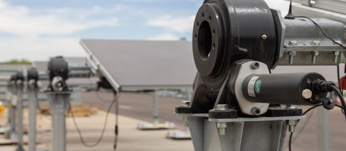
Can you tell solar actuation systems apart? Knowing what’s in an actuator and how it’s tested is paramount.
Solar tracker design has become more challenging than ever as some utility-scale solar projects require larger module arrays, while others contend with complex terrain, unique environmental conditions, and ongoing pressure to control costs.
The actuation system in utility-scale solar trackers, the part that drives the tracker motion, will have an outsized impact on project performance. But many solar professionals may struggle to spot the differences between one actuation system and another. How can you know if the actuation system in your next project will be optimized according to need?
An actuator or drive should not be viewed as a one-size-fits-all component. It’s not a good idea to source actuation systems by comparing some data points on a product spec sheet and assuming that all similarly sized drives are alike. First, be sure to understand the solar project’s structural requirements and the torque demands that will be placed on the actuation system throughout its operating lifetime.
Basics of torque
Torque is a measurement of the force that causes something to rotate around a point. It is most often expressed in kilonewton (kN) for solar applications since one kilonewton represents approximately 224.8 pounds of force (lbf). This measurement is used to size the torque required to rotate something, like a 15,000-lb. array of solar modules attached to a steel tube for example. Torque is also measured by the force needed to hold that same array in a stationary position ensuring the array can survive forces such as wind or imbalances of the array when tilted.
It’s essential for large-scale solar projects to optimize actuation systems according to structural loads and other design parameters. Oversizing the actuation system means taking on unnecessary added costs for the project. Under sizing the system means taking on unnecessary risk, putting plant reliability and longevity in jeopardy.
Why torque matters
During normal operations, single-axis tracker systems can be expected to make small changes in module tilt angle throughout the day to optimize energy output. In the early morning and the late afternoon, the module array may point as much as 60+ degrees from horizontal. The system might also perform backtracking, reversing the tilt angle to reduce energy losses due to shading. Or it might make other adjustments to optimize yield using bifacial modules or to account for variable terrain. All these conditions can apply forces that measure in the hundreds of kN or tens of thousands of pounds of force.
Torque plays a critical role in enabling systems to carry out routine maintenance and respond to extreme weather. Technicians might need to reposition the array to inspect equipment, perform module cleaning, carry out vegetation management, or complete other tasks that increase yield and maintain system uptime. The threat of hail may require the array to be tilted more than 70 degrees to mitigate damage, at the same time ensuring there is enough torque to withstand the increased impact of wind due to the increased tilt angle.
For a system that rotates twice a day reliably for 25+ years, the potential for failure is always present. What do you do if actuator system performance might become less reliable long before the project reaches its expected lifetime?
To safeguard projects from system failure, from having to choose between replacing drives or reverting to a fixed-tilt configuration, product engineers can design in a margin of safety. The safety margin should come from a robust set of field data and thorough, solar-specific testing.
What’s in your actuator?
One of the biggest mistakes you can make when considering what actuator to use would be to evaluate a drive based on a single number and relying on generic engineering and testing not specific to the operating conditions for solar infrastructure. Testing procedures for different applications can vary considerably, even if they generate similar numbers on the product datasheet. You ought to know inputs and outputs. How were the test results derived? How applicable are they to large-scale solar applications?
Product engineers who test actuation systems for solar tracking applications design test plans based on real-world scenarios. Following the concept of Pareto efficiency, engineers look for opportunities to increase loads for one set of scenarios without decreasing loads for other scenarios. This process continues until it reaches an optimal state where no further improvement can be made without an equivalent tradeoff.
Engineers perform static and dynamic testing to measure all the ways that actuation systems perform under various loads. They perform accelerated life testing to detect failure points in the lab faster than would be possible out in the field. They also monitor system performance throughout testing so we can analyze results and improve understanding of how systems will respond to conditions at the project site.
To make sure the system you are designing as tracker manufacturer or specifying as an EPC or developer is optimized according to need, work with suppliers who provide project-level consultation. Make sure your supplier understands solar applications and builds drives specifically for solar infrastructure. Without test results or the underlying data to support the figures you see on a product spec sheet, ask yourself: What else don’t I know about this drive?
Kyle Zech is senior vice president, advanced manufacturing technology at Kinematics, where he leads the development and implementation of manufacturing technologies, systems, and processes. Under his guidance, Kinematics has increased annual production volumes tenfold while simultaneously improving product quality by 4 levels (AGMA). Kyle is named on multiple Kinematics manufacturing technology patents.
Caption: Engineers at Kinematics’ testing lab in Phoenix Arizona, put a solar actuator (component in gold on left end) through dynamic torque tests on Kinematics custom engineered torque dyno affectionately named “Thumper.”


